Well the SmartBoom unit is now installed in the tractor, connected to John Deere's GPS over the serial cable, and plugged into the Flexi-coil switch box using the circuitry I designed and spoke about previously. In dry run tests it appears to work! The system has one weakness and that is that, as far as I know, it does not compensate for the way the sprayer tracks behind the tractor as it turns. I believe SmartBoom assumes the booms are perpendicular to the tractor's direction of travel. For most things I think that will work okay. For spring herbicide we can always manually override it from time to time as the turning wedges get tighter as the we get towards the outside edges of the circle. For fungicide and insecticide it's not quite as critical and I'd rather concentrate on not hitting the bee tents! If it does turn out to be too much of a problem, a computer with 2 serial ports could probably calculate the tracking path and adjust the reported position sent to SmartBoom. I'm looking into this.
Homemade Harness and Plugs
Rather than pay $500 for a SmartBoom wiring harness that I could chop up, and since I couldn't find the necessary plug anywhere on the internet, I ended up machining my own end cover and making my own plugs. Since I did not want to modify the board in any way, I chose not to solder any wires to the board. Instead I made up little plugs with male 2mm pitch pin strips that plugged into the appropriate pins on the female pin plugs that I referred to earlier. Serial is 3 pins on one connector, and the sections come from 4 pins on another connector. I chose not to mess with the master switch at this time, so I didn't bring those wires out of the chassis. I'm just using the Enter button on the front to toggle SmartBoom on or off.


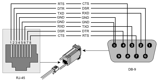
For the serial port I used an RJ-45 jack, wired to Cisco's serial standard, though only using the Gnd, TX, and RX pins:
For the section control signals, I used a standard 4-pin Mic plug. I put a female plug on the SmartBoom, and another female plug on the switch unit, and use a cable with two male ends to connect them, though I could have wired the cable permanently on the SmartBoom end of things. I chose not to since I wasn't sure what length of cable I wanted as I plan to use SmartBoom on other outfits in other tractors doing things like spreading edge with the Valmar.
Tying it all Together
Here's a pic of the inside of the switch unit. This is my spare switch unit and when I get the replacement toggle switch I need, I'll wire it all up and post pictures of that here. For now you can see the mic plug and the little tiny circuit board wrapped in a nice electrical tape blanket. The colored wires will attach to switches 1,2,3, and 4, and the black wire will go to ground.


Inside the tractor, a 4-conductor cable attaches from the back of the SmartBoom to the Switching unit:

As you can see, it's working. Here it's driving the sections. Even though the switches are down, the red lights are on, showing that the section is operating. The main on/off switch still works so I can easily shut down the sections if I need to quickly stop things. Here's a picture where the sprayer is overlapping and is only running two sections:

Pretty exciting! In a few days we'll try it with foam markers and water and see if we can get it tuned right.


