Thursday, 20 October 2016

Center Pivot Simulator

Here's a quick preview of a little project I'm working on. It's a software simulation of a center pivot irrigation machine. I'm using Python and PyQt to build this in a flexible and fairly rapid way, and to allow this simulation to run on other platforms easily.

The purpose of this simulation is to provide a platform for experimenting with my remote pivot control system. The simulation has two parts, which I detail below.

Simulation of pivot's physical characteristics

The first part of the simulator simulates the physical characteristics of the pivot. This includes analogs of the control wires that go down the length of the pivot, the end tower's movement, the over-watering timer on the 2nd-last tower, the end gun solenoid, the lights on the center and end tower,and the water in the pipe. Also simulated is the safety return line, and the ability to simulate faults in the towers. The simulator drives itself around the virtual field and has a virtual GPS receiver on the end tower, and also an adjustable resolver that simulates the position ring found on the neck of some pivots.

This part of the simulation does not contain any control panel. The GUI component, shown above, does include buttons to manually activate various circuits, which I used to test the pivot simulator. Thing such as the GPS receive or the resolver ring have no effect on the simulator. They are for use in higher levels of the simulator, such as a simulated computer panel.

Simulated basic pivot control panel

All pivots have at least a basic control panel mounted to them that let you set a direction for the pivot to go, set the duty cycle (speed) of the end tower, detect water, handle faults, etc. All this is simulated in a panel simulation, shown in the screenshot above. I have simulated a basic, analog pivot control panel here, not unlike the Zimmatic Basic panel. The reason I went to the work of implementing this is because I think the easiest way to control a pivot from a fancy remote internet-connected thing is to use the existing panel which already has a safety system, contactors, etc.

Yet to implement is the end gun control system, the end tower timer, and the autostop/autoreverse whiskers.

My goal is to simulate the basic panel with enough fidelity that a real pivot could be controlled by interfacing with the panel in the same way. Using relays to control the on/off switch, the forward/reverse buttons, etc.

Wednesday, 6 April 2016

Raven SmartBoom Part 3

Well the SmartBoom unit is now installed in the tractor, connected to John Deere's GPS over the serial cable, and plugged into the Flexi-coil switch box using the circuitry I designed and spoke about previously. In dry run tests it appears to work! The system has one weakness and that is that, as far as I know, it does not compensate for the way the sprayer tracks behind the tractor as it turns. I believe SmartBoom assumes the booms are perpendicular to the tractor's direction of travel. For most things I think that will work okay. For spring herbicide we can always manually override it from time to time as the turning wedges get tighter as the we get towards the outside edges of the circle. For fungicide and insecticide it's not quite as critical and I'd rather concentrate on not hitting the bee tents! If it does turn out to be too much of a problem, a computer with 2 serial ports could probably calculate the tracking path and adjust the reported position sent to SmartBoom. I'm looking into this.

Homemade Harness and Plugs

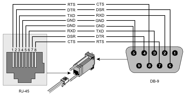
Rather than pay $500 for a SmartBoom wiring harness that I could chop up, and since I couldn't find the necessary plug anywhere on the internet, I ended up machining my own end cover and making my own plugs. Since I did not want to modify the board in any way, I chose not to solder any wires to the board. Instead I made up little plugs with male 2mm pitch pin strips that plugged into the appropriate pins on the female pin plugs that I referred to earlier. Serial is 3 pins on one connector, and the sections come from 4 pins on another connector. I chose not to mess with the master switch at this time, so I didn't bring those wires out of the chassis. I'm just using the Enter button on the front to toggle SmartBoom on or off.

For the serial port I used an RJ-45 jack, wired to Cisco's serial standard, though only using the Gnd, TX, and RX pins:

For the section control signals, I used a standard 4-pin Mic plug. I put a female plug on the SmartBoom, and another female plug on the switch unit, and use a cable with two male ends to connect them, though I could have wired the cable permanently on the SmartBoom end of things. I chose not to since I wasn't sure what length of cable I wanted as I plan to use SmartBoom on other outfits in other tractors doing things like spreading edge with the Valmar.

Tying it all Together

Here's a pic of the inside of the switch unit. This is my spare switch unit and when I get the replacement toggle switch I need, I'll wire it all up and post pictures of that here. For now you can see the mic plug and the little tiny circuit board wrapped in a nice electrical tape blanket. The colored wires will attach to switches 1,2,3, and 4, and the black wire will go to ground.

Inside the tractor, a 4-conductor cable attaches from the back of the SmartBoom to the Switching unit:

As you can see, it's working. Here it's driving the sections. Even though the switches are down, the red lights are on, showing that the section is operating. The main on/off switch still works so I can easily shut down the sections if I need to quickly stop things. Here's a picture where the sprayer is overlapping and is only running two sections:

Pretty exciting! In a few days we'll try it with foam markers and water and see if we can get it tuned right.

Saturday, 2 April 2016

Cheaper Replacements for CaseIH 2-wire Inductive Proximity Sensors

$200 Sensors

On CaseIH combines of recent vintage, there are several sensors throughout the combine that measure shaft speed or chopper knife position. Years ago shaft speed sensors were hall-effect sensors and required a magnet on the shaft to trigger the switch inside the sensor to generate a ppm signal. Now usually inductive proximity sensors are used. These sensors can be placed near gear teeth to measure speed, or they can simply indicate proximity to metal, which can help sense position. For example if the chopper knives are not retracted when the chopper is switched to low speed on Case combines, the computer alarms. There's a proximity sensor on the lever. These sensors are easy to identify because they are round and threaded, stick close to a moving part, have a wire sticking out, and usually have an LED on them that glows and blinks as sensor detects metal.

Proximity sensors come in various diameters and usually come with 3-wire plugs (or 4 wires). There are wires for power and ground, usually 12V. The third wire is essentially the emitter leg of a transistor. There are two kinds of sensors, NPN and PNP just like transistors. Also the sensor is either normally closed or normally open when not detecting any metal. When the circuit is closed, the LED will glow and the emitter wire will be connected to ground in the case of NPN, or 12V in the case of PNP. Either NPN or PNP can be adapted for use in these Case machines. However typically the sensors are normally closed (opposite of the sprayer speed sensor, which is normally open), meaning the LED glows when there's no metal nearby.

Also sensors have different specs for distance. Normally sensors are about 8mm maximum distance, but some sensors are rated at no more than 2mm and some are rated up to 20mm. I believe that the CNH sensors are standard distance, or about 8mm.

The sensor I have on hand is CNH part number 87342073, chopper speed sensor. It's 18mm in diameter and looks something like this:

Disclaimer: I removed the Deutsch plug and put it back on for this picture, but the wires might be backwards. Look at an existing sensor on your own machine to see the proper polarity. I'll edit this post with the correct polarity at a later date.

As you can see, the sensor has only two wires. We can power it up on the bench by applying 12v to the yellow wire and Ground to the blue wire. I find that it's a normally closed sensor. The LED glows when it's not near metal, and goes out when it is near metal. The distance seems to be about 8mm, which is standard for this sort of sensor. According to Case's parts site the same sensor is used for the following things:

  • Chopper speed sensor
  • Ladder position sensor
  • Unloading auger position
  • Chopper knife position
  • Shoe shaker speed

How to Convert 3-wire to 2-wire sensor

Two-wire sensors are easily made from three-wire sensors. You can buy off-the-shelf two-wire sensors, but 3-wire sensors are more versatile and useful for other applications besides the combine. Also if the combine computer requires a specific current characteristic, the three-wire sensor is easy to configure. Plus they are also slightly easier to find. I chose to buy the 18mm shielded, normal length, normal detecting distance, NPN, normally-closed sensor from Automation Direct. Part number PNK6-CN-3A. In the future I'll buy the PNP variety, since they will work better as speed sensors on my sprayer and air drill. Either way, this sensor is about $20 USD. Here's what it looks like next to the CNH sensor:

The way a computer reads a two-wire sensor is by sensing current. When the sensor is closed (not next to metal), a small amount of current flows through the sensor. When the sensor is open (next to metal), the current flow drops to zero. This is how the computer senses whether the sensor is near metal or not. As the current pulses the computer can calculate pulses per minute and thus RPM. I don't know what the range of current variation the computer can work with is. It would depend on how they designed their system.

Analyzing the Sensors' Characteristics

We can figure out how much current the CNH sensor uses with a multimeter in series with the power. According to my multimeter, the current flow is about 7 mA (0.007 amps) at 13.8 V. Using ohms law we can determine that the internal resistance must be about 2000 ohms. Our goal is to make the Automation Direct sensor have similar current flow characteristics.

Internally the CNH part must be either an NPN or PNP system but the emitter is used to light up the LED and also possibly tied to an internal load resistor, and not passed out externally to the sensor body. Again all that matters to us is how much current flows, and that the sensor is normally-closed.

On the bench we can plug in the AD sensor to it's power wires. It has its own LED that operates the same as the CNH sensor. When it's not near metal the LED glows, and goes out when it's near metal. We can put the multimeter in series with the power wire and we find that this sensor behaves similarly to the CNH sensor, even if we ignore the third wire entirely. When the LED is on, it consumes about 5 mA of power, and when it's off, there is no current flowing. It's possible that this would work as is on the combine, just ignoring the third wire entirely (cut it off and tape it up). However we can use it with a resistor to make this sensor very close to the CNH sensor in terms of current signalling.

Adding Load

Since the current draw is lower on the AD sensor, that means the internal resistance is higher than the CNH one. The AD sensor is about 2500 ohms, and the CNH sensor was just under 2000 ohms. Since the third wire is like a transistor emitter, and the sensor I bought was NPN, when the LED is on, the third wire is connected to ground. So an appropriately chosen resistor between the 12V power and the third wire will add a small load to the sensor, and bring the current draw up to the 7 mA the CNH part has. If the sensor was PNP, the resistor would go between the third wire and ground. Either way it would work, provided the sensor is normally closed since that's what the CNH sensor is. If you use normally-open, it would work for speed sensing, but some of the sensors like ladder position or chopper knife position wouldn't work at all.

We can calculate an approximate resistor value using this formula:

1/2000 = 1/2500 + 1/x

Solving for x, we get 8000 ohms. That's pretty close to 10k, which is a common size. And testing on the bench shows that 10k works pretty well.

Now all we need is solder the resistor to the correct wires (load and ground for PNP-type, or load and 12V for NPN type), cover it in shrink wrap or tape, connect it into the Deutsch plug (possibly using the old, non-working sensor's plug), and we've now replaced a $200 CNH part with a $20 Automation Direct NPN-NC or PNP-NC sensor plus a few pennies for a 10k resistor. Later this season I'll wire one up and do a follow up post.

Wednesday, 16 March 2016

"ISO-compatible" Speed Sensors

Many of our machines, including the air drill and the sprayers, have a 3-wire sensor to detect speeds. On the Air drill there is one on the cart wheel to detect ground speed, and there's another on the fan to detect fan RPM. On the the air cart and the sprayers they all use the same sensor, CNH part number 13976. The parts catalog calls this an "ISO-compatible speed sensory." But just what is this sensor?

Some online sources call this a hall sensor but that's not correct. It's actually an inductive proximity sensor. I'm not sure of all the specifications for sensing distance, etc but I do know it's a fairly standard 12V inductive sensor inside, but with a twist and some additional circuitry.

CNH Sensor Characteristics

When the sensor is not detecting metal, there is about 2.9k ohms resistance between the white wire and ground. The purpose of this resistance is to allow the computer to detect whether the sensor is plugged in or not or the wire is broken. A normal NPN sensor would ordinarily have either very high impedance between sensor and ground when the sensor is not triggered (open) and very low impedance when triggered (closed). This would make it difficult for the computer to quickly and easily detect if the sensor was attached. If the sensor is open that could mean either the sensor is unplugged, or maybe it's stopped between gear teeth. This resistance acts as a sentinel.

When the sensor is detecting metal, the resistance between the white wire and ground goes to between 200 and 260 ohms. It does not go to zero, which would be the normal behavior for an NPN sensor when in closed position. The reason some resistance is desirable is that this allows the computer to detect a short-circuit on the white wire.

Not Actually an NPN Sensor

Some additional circuitry is thus required to adapt an off-the-shelf proximity sensor to be "ISO compatible. My first attempt involved using an NPN proximity sensor with a single 2.9k resistor between white and ground. This worked sometimes but only if the sensor was in the open position when the computer booted up. Otherwise it said there was a short on the speed sensor. This clued me into the fact that the closed position isn't a short to ground but rather about 200 to 260 ohms.

We can get behavior identical to the ISO-compatible CNH sensor by using an NPN normally-closed proximity sensor with a nFET, or a PNP normally-open proximity sensor with a regular NPN transistor, and three resistors in either case. Here are the circuit diagrams:

The idea behind these circuits is tie the signal wire to ground through a 2.9k (or 3k) resistor. This ensures that when the sensor is in one state (we shall call it "open" though it may be exactly opposite of the inductive sensor state depending on whether the sensor is NPN or PNP), the resistance between white and ground is 2.9k. When the transistor is switched on, this connects the white wire to ground through a 300 ohm resistor, which means that the 2.9k and 200 ohm resistors are now connected in parallel, which yields an impedance of around 260-270 ohms on the white wire to ground. This is the "closed" state.

It really does not matter if using a normally open or normally closed sensor for this purpose. The number of teeth on the gears is always the same as spaces, so it doesn't matter if we're counting spaces or teeth. The speed is the same. But to match the CNH behavior exactly, normally-closed for NPN, and normally-open for PNP. (Did I get that right or exactly backwards?)

Unfortunately, with the NPN sensor (Bought from Automation Direct, Part number PNK6-CN-3A), an NPN BJT transistor won't work. I think this is because the impedance of the NPN proximity sensory load wire when closed is high enough that current still flows through the transistor. In other words even though the proximity sensor pulls the voltage down, there's still current flowing through the transistor. Electricity may take the path of least resistance, but it does so equally. Current flows through the proximity sensor load wire and the transistor at the same time. Thus the transistor never switches.

An N-type mosfet does work in place of the BJT, however, as it has super-high impedance and switches on voltage, not current. So the load wire on the inductive sensor is able to pull the voltage down low enough to switch the mosfet off. Thus the circuit works and we get the desired impedance levels. However mosfets are extremely sensitive to static and other voltage events and burn out easily. So I expect the mosfet-driven arrangement will not be reliable. (Update Sept 12, 2016: As of now the sensor is still functioning so it seems to be reasonably robust.)

The most reliable arrangement may be the PNP inductive sensor, such as Automation Direct part number PNK-AP-3A, connected to the base of a normal NPN BJT transistor, held to ground by a 10k resistor.

Conclusion

So rather than buying an expensive CNH part to replace a bad sensor, an off-the-shelf 12V normally-open PNP sensor can be used with some simple additional circuitry of a transistor and 3 resistors. What could be more simple?! CNH's parts business likely remains secure.

Here's a picture of the sensor, embedded in the 22-mm plastic housing that the old sensory was in. I should have bought the longer sensor. The short sensor was too short, so I pulled apart the original, failed sensory and reused the 22-mm plastic housing. In the future I'll just use the longer PNP sensor, and some washers.

And here's a picture of the little circuit, between the Deutsch plug and the sensor, before I encased it in silicone sealant and wrapped it up nicely:

Sunday, 21 February 2016

Raven SmartBoom Part 2B

Solid State Interface

Rather than use Relays which are prone to mechanical failure and which generate voltage spikes down the wires coming from the SmartBoom (and though the SmartBoom is robust enough to deal with it), it occurred to me that MOSFET or BJT transistors could be used to convert the 12V signalling logic to the switching logic used by the Flexicoil switch box.

The reason to use MOSFETs instead of traditional BJT transistors is that MOSFETs can switch on voltage, 12V easily, whereas BJTs switch on current. Either way would work of course. With BJT transistors, a resistor would limit the current into the transistor. Theoretically no resistor would be needed with a MOSFET. Though in either case, a resistor would need to tie the gate or base to ground (though I have a hunch the SmartBoom driver chips already do that), to keep the transistor off when the voltage goes away, such as when SmartBoom not connected to the switch unit at all.

Here's a schematic for using N-type MOSFETs. BJTs would be similar, though perhaps the resistor values would differ:

I have plenty of transistors on hand; I don't think I have any FETs. I'll run some simulations in 123d-circuits and then decide. I can order FETs easily and quickly online.

Update

Looks like normal BJT transistors work fine with similar resistor values to the ones I would have used with FETs. With a 100k resistor to pull the Base to ground, and a 10k resistor on the input signal (limiting current to 1.4ma) to the base, it should work. In simulation on 123d-circuits, current flow even at signal voltages as high as 30V are very low. And the current that flows through the internal pull-up resistor inside the switch box input line is very small. So FETs are probably overkill and besides I don't have any on hand. I don't know how much current from the input line to ground is required for the processor to see a low logic level; depending on the transistor gain I might have to use a lower value resistor on the 12V input lines. That'd be one benefit to the FETs--they switch on voltage so the resistor value matters a lot less. Since the input line to the microprocessor is probably tied to a base of a transistor or the gate of FET internally, I doubt much current, if any, is required to change the logic level. So I'll try it as I've described.

Here's a picture of my little circuit board with NPN transistors and some resistors. The input wires (12V signals) come in on the light colored wires, and the solid color wires connect to the signal side of the section switches. When 12V is applied to the input wire, the corresponding solid wire is pulled to ground through the transistor:

This little prototype board works out pretty well. The two rails down the center are ground (black wire). The transistor emitter is tied to ground as well, with the base pulled to ground with 100k, and the 12 signal attached to the base also through a 10k resistor. The collector of the transistor (middle wire) is the output to the switch.

Further Update

The circuit works! I can apply 12V to any of my four input lines and it pulls the signal low just like flipping the switch does.

Friday, 19 February 2016

Raven SmartBoom Part 2

Just a quick progress report on making the Raven SmartBoom work with our old New Holland SF216 sprayer. After figuring out how the SmartBoom signals work, the next step was to interface with the old controller our sprayer uses. I figured the easiest way would be to tie into the section control switch box.

After opening the switch box it because clear that whatever voltages the switches were using, it wasn't 12V. The switch box itself is a bank of switches tied to a microcontroller. This microcontroller communicates with the master sprayer controller over some sort of RS485 bus. I don't know what protocol it uses, but I imagine it's some master and multiple slaves system (maybe modbus?) as you can attach more than one switch box to the controller and other devices also, including other automatic section control systems.

The ideal, non-invasive thing to do would be to use an arduino to interface between the 12V signals coming from the SmartBoom and talk directly to the main controller over this bus, much like the Flexi-coil native section control system does. However the simpler thing to do would be to use a bank of relays to act in parallel with the switches. So that's what I implemented.

Using Relays

The toggle switches are all single-pole double-throw (three conductors), but the off side of the switch isn't connected to anything. The switches switch digital logic inputs on the microprocessor. A resistor holds each line to 5 volts (high). When the switch is thrown to the "on" position, it shorts this signal to ground. This makes it very easy to interface with. Here's a simple diagram that shows how relays can bridge between the 12V signal and the pull-down signals that go to the switches:

The fact that each switch shorts the section signal to ground makes the wiring of the relays very simple. All the grounds from every coil are tied together, and also the common part of the normally-open contacts on the relay itself. These are tied to the main ground coming into the box through the normal wiring harness. The normally-open contact can wire directly to the on side of the toggle switch. This means we need only bring 4 12V signals in from SmartBoom (we only have 4 sections on the sprayer; more additional wires could drive additional relays for more), and only four wires need to connect to the circuit board itself. Here's a picture of the circuit board and the relay bundled up underneath with the four signal wires ready to attach (note the broken and missing switch).

Normally it's a good idea to have a diode to absorb the current generated when the relay is switched off and its coil discharges. In this case I have no protection because the driver circuits in the SmartBoom are already protected and designed to drive solenoids and other forms of relays. Besides a very robust driver chip, each signal line is protected in the SmartBoom by a beefy Transient Voltage Suppression diode, or TVS IC. And since the other side of the relay is merely connecting to ground, we don't need to do anything further to protect the circuit on the switch box side of things.

So I'm just about ready to put all the pieces together, except that while drilling the hole in the side of the switch box the drill press gave everything a good spin and unfortunately the main toggle switch broke. So I am waiting for a replacement toggle switch which I will solder onto the circuit board in place of the broken one. Even when SmartBoom is operating, the main toggle switch is active and can be used to shut off the booms.

Wednesday, 10 February 2016

Adding GPS-driven Automatic Section Control to the Sprayer

Recently we were considering buying a second sprayer to have, partly as a spare, and partly to ease the burden of moving between crops in terms of rinse out.  Also with two different varieties of valuable hybrid seed canola this year, I liked the idea of having one sprayer for each variety so it would be easier and safer when we have to go back and forth between the two kinds of canola.  So while looking for a second sprayer I wondered what the feasibility would be of switching rate controllers to something we could install such that two different brands of sprayer could be compatible with the same in-tractor setup.  So I started researching what Raven had available.  Turns out it the cost of an upgrade would be very expensive.  Also we found a second sprayer that was identical to the current one so our existing controller could be used.

Raven SmartBoom

However, while researching I discovered an old, obsolete product from Raven called SmartBoom which is a fairly standalone solution for doing automatic section control:

From what I could tell, all it needed was a RS232 GPS input signal, which I already get off of our StarFire receivers, and it provides a 12V signal for each section to turn it on and off.  The 12V signal can provide up to 2 amps as well, so it can directly drive something like a magnetic clutch.  I was intrigued by this unit because it is simple and it should be able to, with a bit wiring, drive our existing sprayer controller's boom segment signals.  After a quick phone call to our local Raven rep in which he assured me that indeed this would not work the way I was thinking and I needed a full Raven system from stem to stern (I think he misunderstood what I was asking about) , I placed an order online for a steal of a deal for the SmartBoom.

I now have the SmartBoom and I've tested it out and it does indeed work like I want it to.  Unfortunately I could find no information on the pinouts from this thing and Raven wants $500 for a basic cable that is nothing but a big plug and bunch of pigtails to tie into your existing sprayer console. So by trial and error I figured out what the pins on the control output do and thought I'd share it here

SmartBoom Control Plug Pinout

Here's a diagram of the control plug on the SmartBoom:

The pins are labeled according to what they do. S means signal, Gnd is ground, MS is master switch, and the 3v and 12v pins are live with that voltage.  The numbers in parenthesis refer to a connector grid on the main board inside.  The plug itself is soldered to a daughterboard which interfaces with the mainboard using a standard  2mm pitch pin grid that's 3 by 7 pins.  The reason I mention this is because Raven wants $500 for their shortest cable that attaches to this plug.  I've been unable to locate a mating plug anywhere on the internet (if you can find me an IP67 circular plug (24 mm across) with 20 contacts, please let me know!), so I intend to solder my own wires directly to the board, bypassing the plug entirely, and will solder onto the ends of the pins in this grid where they stick through the board.


What the pins do

I'm not sure what the 12v pins are for, but the 3v pin and the MS pin form a master switch toggle.  When they are shorted together SmartBoom is in automatic mode, controlling sections as it desires.  When not shorted, SmartBoom sends no signals, allowing the normal section switches to work on the cab controller box.

The pins labeled S1, S2, S3 and so forth refer to the section control signal pins.  In Sprayer mode, when section 1 is active, S1 will be 12V.  When the section is off, the pin will be 0 volts.

So it's pretty simple, really.  All I need to do is run my own cable from the toggle switches into this box to the appropriate pins.  I'll show how I do this in another post.  Also the form factor of this box is really awkward, as far as mounting it where I can interact with the screen on it.  However only 5 wires drive the screen (it's driven entirely over a serial connection actually), so it's easy to make a cable that let's me place the screen anywhere I want. I plant to make a little box for the screen and run a cable down to the main unit which I'll probably place on the floor or against the side of the tractor's console.

So in the next blog post I'll talk more about how I will do that and probably document one or two other things about the circuit board.

Friday, 22 January 2016

Arduino Fertilzer Flow Meter update

UPDATE: had to fix some html entities in my posted code. Hopefully it's okay. I've since posted this code on github, so check it out at https://github.com/torriem/ppmreader/.

I've received a number of comments on the Youtube video about the flow meter I was working on. Here's the video:

In the end the project was a failure. My electric valve hack job was just too hard to work with. Also I never could dial in the PID look quite right. In the future I will look at this again, using a valve more designed for this purpose. PID tuning is really hard! Especially when the system responds in non-linear ways. For example the plastic hose expands slightly under pressure, so when you first crack the valve you get a spurt of high-speed fluid which then drops off quickly. Putting the flow meter before the valve in the high pressure seems to be the most logical thing to do.

A number of Youtubers are saying they want to see my code. Unfortunately I don't see how my code in its entirety is going to help most of them. However,I would like to post the code that I use to actually read the flow meter.

Ostensibly it's a very easy thing to do. Most flow meters use a hall effect sensor, so every time the wheel turns around you get so many edges in a high/low signal. So all you have to do is measure the elapsed time between these pulses and you've got it!

Except it's not quite that simple. There's one problem especially that is vexing. Suppose you are spinning at a particular rate (measured in pulses per minute). Suddenly the wheel stops turning. If you are just measuring elapsed time then you'll have to wait an indefinite amount of time to see if either the wheel is stopped, or maybe it's just turning really slowly. There are probably a number of ways to solve this problem, but I find the simplest way is to just define a time cutoff. If a certain amount of time has passed without a pulse, we just set our speed to zero. That works for most real-world applications.

Other improvements and complicates include using a moving window to smooth out the average PPM that you're getting.

Anyway I've created a simple class library that makes working with measure average pulse per minute fairly simple and easy. It works with anything that generates a PPM signal. So hall-effect flow sensors, wheel speed sensors, etc. Here's the code and then I'll share a few things about using it:

ppmreader.h

/* Licensed under the MIT license
 * Copyright 2014 Michael Torrie
 * torriem@gmail.com
 */

#ifndef __PPMREADER_H__
#define __PPMREADER_H__

#define TICKS_PER_CALC 10

class PPMReader
{
protected:
        uint32_t last_interrupt;

        uint32_t last_times[TICKS_PER_CALC];
        uint8_t last_time;

        uint16_t  ave_ppm;

public:
        uint8_t   record;
        uint32_t  totalpulses;

        uint16_t zero_time; //ms since last interrupt to zero ave ppm (stopped)
        uint16_t ppm_cutoff; //ppm at which we may as well just go to zero.
                             //probably not needed check() has other better ways

        PPMReader();
        uint16_t get_ppm(void);
        void reset(void);
        void on_trigger(void); //must be called from a static isr wrapper func
};
#endif

ppmreader.cpp

/* Licensed under the MIT license
 * Copyright 2014 Michael Torrie
 * torriem@gmail.com
 */

#include "ppmreader.h"
#include <limits.h>

//TODO should this be configurable by the caller?
//This sets up a moving average so that what was seen
//before is less important.

static const double coeff = 0.10;

void PPMReader::on_trigger(void)
{
        uint32_t now;
        uint32_t delta;
        uint16_t ppm;

        if (record)
                totalpulses ++;
        /* after the first 10 ticks, this will calculate an average
         * speed over the last 10 ticks each tick.  It's a bit slower
         * but it's going to be a lot smoother.  Hopefully eliminates
         * spikes
         */
        now = micros();

        /* Not sure if this is really necessary but wait for the ring
         * buffer of last times to be completely full (at least 
         * TICKS_PER_CALC number of ticks) before starting calculations.
         */
        if (0 == last_times[last_time]) {
                last_times[last_time] = now;
                last_time = (last_time + 1 ) % TICKS_PER_CALC;
                return;
        }

        ppm = (uint16_t)( TICKS_PER_CALC *
                /* convert microseconds to minutes */
                1000000 * 60 /
                /* divided by microseconds passed */
               (now - last_times[last_time]) );
        last_time = (last_time + 1 ) % TICKS_PER_CALC;

        /* smooth ppm using a moving average. */
        ave_ppm = ppm * coeff + ave_ppm * (1 - coeff);

        last_interrupt = millis();

}

uint16_t PPMReader::get_ppm(void) {
        uint32_t now;
        uint16_t max_ppm;

        //TODO possibly turn off interrupts here
        //I'm tempted to leave them on though, as if the ISR runs
        //durring this routine, it's not a big deal, but it could
        //introduce some noise.

        if (ave_ppm < ppm_cutoff) {
                ave_ppm = 0;
                return;
        }

        /* if too much time has elapsed since our last interrupt,
         * let's zero out the average pulses/minute
         */

        now = millis() - last_interrupt;

        if (now > zero_time) {
                /* if a certain amount of time has passed without an
                 * interrupt, assume we're stopped, since we're going
                 * so slow as to just as well be stopped.
                 */
                ave_ppm = 0;

        } else {
                /* calculate the maximum ppm, given time since last
                 * interrupt
                 */
                max_ppm = 60000 /*ms in a minute*/
                          / now; //leaves us with per minute

                /* if an interrupt by now would result in a ppm that
                 * is already lower than the current running average,
                 * at least we know we're slowing down, so go ahead and
                 * bring the average down
                 */
                if (ave_ppm > max_ppm) {
                        ave_ppm = max_ppm * coeff +
                                ave_ppm *
                                (1 - coeff);
                }
        }
}

PPMReader::PPMReader ()
{
        totalpulses = 0;

        //default values that can be overridden
        ppm_cutoff = 50;
        zero_time = 1000;
        record = false;
        reset();
}

uint16_t PPMReader::get_ppm(void) {
        uint32_t now;
        uint16_t max_ppm;

        //TODO possibly turn off interrupts here
        //I'm tempted to leave them on though, as if the ISR runs
        //durring this routine, it's not a big deal, but it could
        //introduce some noise.

        if (ave_ppm < ppm_cutoff) {
                ave_ppm = 0;
                return;
        }

        /* if too much time has elapsed since our last interrupt,
         * let's zero out the average pulses/minute
         */

        now = millis() - last_interrupt;

        if (now > zero_time) {
                /* if a certain amount of time has passed without an
                 * interrupt, assume we're stopped, since we're going
                 * so slow as to just as well be stopped.
                 */
                ave_ppm = 0;

        } else {
                /* calculate the maximum ppm, given time since last
                 * interrupt
                 */
                max_ppm = 60000 /*ms in a minute*/
                          / now; //leaves us with per minute

                /* if an interrupt by now would result in a ppm that
                 * is already lower than the current running average,
                 * at least we know we're slowing down, so go ahead and
                 * bring the average down
                 */
                if (ave_ppm > max_ppm) {
                        ave_ppm = max_ppm * coeff +
                                ave_ppm *
                                (1 - coeff);
                }
        }
}

PPMReader::PPMReader ()
{
        totalpulses = 0;

        //default values that can be overridden
        ppm_cutoff = 50;
        zero_time = 1000;
        record = false;
        reset();
}

How to use it

Using the code is straight foward. Instantiate a PPMReader (it's a class because in my code I used two of them). Create a static ISR trigger callback function in your code that call's the PPMReader object's on_trigger() method. Once the ISR is installed, the PPMReader will automatically count. At any time you look at it's public totalpulses variable to read the total since the last reset. This is how you can do things like measure a liquid.

To get a reading of the current PPM, call the get_ppm() function. Though the interrupt service routine is doing some average calculations on the fly, if the flow meter stops, then the ISR isn't being triggered, so get_ppm() will do cutoff detection and clean up the average accordingly.

I hope this helps the Youtube commenters. And please Google, stop creating Google+ profiles when people comment. You said this was not going to happen anymore but it still is!