It's interesting to see that it really does work! The first half of the video simulates a single day as the shadow moves across from left to right. Can you figure out the approximate date, or at least two possible approximate dates? The second half of the video shows what the shadow looks like at 12 noon over the period of an entire year.
Thursday, 30 January 2014
Simulating a sundial on Google Sketchup
Craig discovered today that you can simulate a sundial with Google Sketchup. So he put together a nice little sundial that replicates the one I saw in Israel, which uses my generated diagram. And it works! This is a simulation of the first sundial.
It's interesting to see that it really does work! The first half of the video simulates a single day as the shadow moves across from left to right. Can you figure out the approximate date, or at least two possible approximate dates? The second half of the video shows what the shadow looks like at 12 noon over the period of an entire year.
It's interesting to see that it really does work! The first half of the video simulates a single day as the shadow moves across from left to right. Can you figure out the approximate date, or at least two possible approximate dates? The second half of the video shows what the shadow looks like at 12 noon over the period of an entire year.

Tuesday, 28 January 2014
A More Precise Sundial
While reading online about sundials, I stumbled on this photograph of a precision sundial on Wikipedia:
Instead of having a perfect grid with an analemma in the center for calculating adjustments to solar time, the analemma is built into the grid itself. Of course to make it readable they had to split the year into two parts and put one part on one half cylinder, and the other part on another. But it's highly accurate and easy to read.
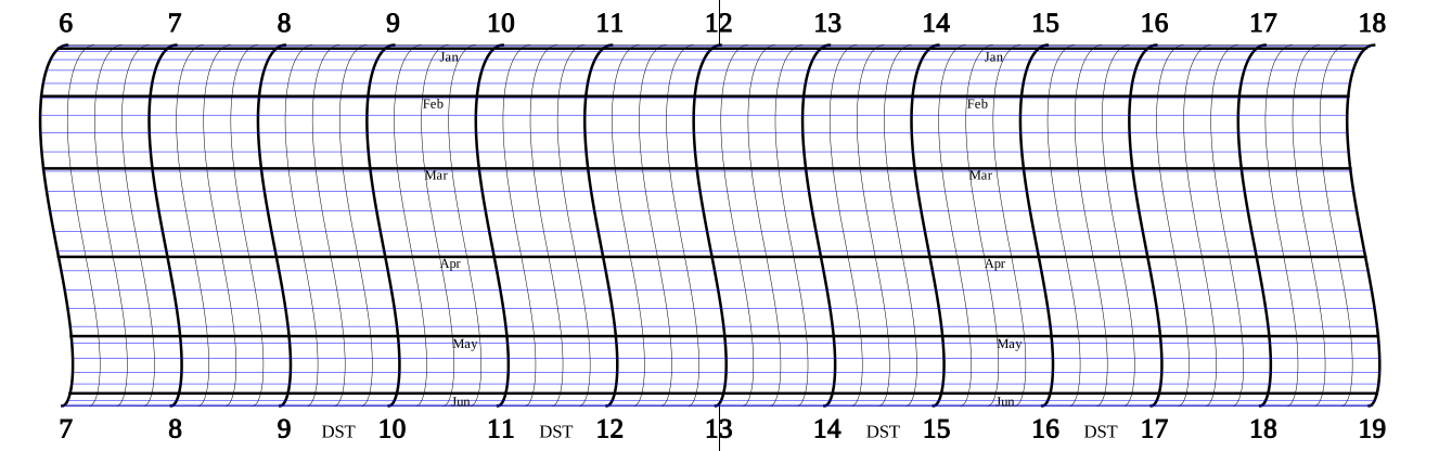
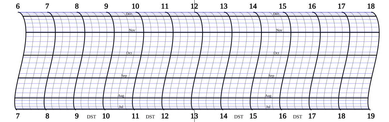
I thought, I have everything I need to generate this type of diagram. I have the analemma algorithm, so all I need to do is replace the vertical hour and minute lines with copies of one-half of the analemma diagram. So an hour of modifications later, my Python program can now output these nicer, cleaner charts (links in captions to svg):
These charts are marked with weeks too, with each small blue line marking a Sunday. Of course this will only be right for 2014. But the chart could be marked in other ways, such as each day even, if the chart were scaled up large enough. That'd be very accurate.
I will post code soon.
 |
| http://commons.wikimedia.org/wiki/File:Precision_sundial_in_B%C3%BCtgenbach-Belgium.jpg |

I thought, I have everything I need to generate this type of diagram. I have the analemma algorithm, so all I need to do is replace the vertical hour and minute lines with copies of one-half of the analemma diagram. So an hour of modifications later, my Python program can now output these nicer, cleaner charts (links in captions to svg):
 |
| First half (svg) |
 |
| Second half (svg) |
I will post code soon.
Monday, 27 January 2014
Cylindrical Sundial
While traveling in Southern Israel, I happened across a sundial at Mitzpe Ramon. The sundial was essentially a half cylinder inclined on an angle so that a horizontal rod passing through the cylinder's axis would cast a shadow on the face of the dial, reading time. Unlike circular flat sundials, this one didn't have any curved lines. Reading the time was simple. The rod cast a shadow over the hour, and a round sphere on the rod cast a shadow that would indicate the date. An analemma diagram in the middle calculated an adjustment to the time based on the time of year. This adjustment is needed because the Earth's orbit is elliptical, the sun appears to move slightly east or west when viewed at the same clock time each day. Also as the earth's axis progresses, we get tilt relative to the sun, so the sun at high noon will be highest in the summer on June 21, and sink nearly 47 degrees to the south in winter on Dec 22. The analemma diagram shows these motions and lets us calculate corrections to the time.
Here's a picture of the sundial:


The analemma diagram is really an xy plot of the sun's angle in the sky at noon vs the distance from exactly straight overhead, in minutes. If you were too look at this sundial at exactly noon, local time, the little round shadow would be right on the diagram, at the location specified by the date.
Because time zones are 15 degrees of longitude wide, unless you live in the very center of the time zone, solar noon when the sun is overhead and clock noon won't be lined up, even with the corrections from the analemma chart. This is compensated for by rotating the entire assembly about the cylinder's axis to program in a fixed time that can be added or subtracted always. In Israel, this was a subtraction of about 15 minutes, which you can see as the bottom 1 PM mark is slightly to the right of the fixed piece of the stand. This offset can be calculated in degrees with the following formula:
offset = timezone * 15 - longitude
To convert that to minutes, just divide the offset angle by 15 degrees/hour, and multiply by 60 minutes/hour.
y = tan (angle) * radius
The maximum and minimum Y is tan(-23.45)*r and tan(23.45)*r, respectively.
For each day of the year we can, using the formula for converting angle to Y axis locations, plot each day on the same grid we divided into hours. As we go we can label the point on the analemma diagram for the first day of each month, which is needed to determine the approximate date from the shadow. At most points on the analemma path, there are two days that have the same sun declination (or very similar), but nearly opposite minute corrections.

Above is the generated chart, made from my Python script. If scaled up at the same aspect ratio, the chart can be used at any size if wrapped into a half cylinder. The image here is just a JPEG image, but click on it to see the the original, downloadable, and completely scalable, SVG file.
I'll post my python code eventually. Also I want to make a html/javascript page that can generate the diagram at runtime in the browser.
Here's a picture of the sundial:
How to read the time
In the close-up shot we can see that the shadow is falling on about 9:45am, and if draw a line from the ball's shadow to the analemma diagram, we can see that the current date is either sometime in the first week of February, requiring an addition of nearly 12 minutes to the time, or sometime in the second week of November, which requires subtracting about 16 minutes from the time. This picture was taken in November, so the time is about 9:30am.The analemma diagram is really an xy plot of the sun's angle in the sky at noon vs the distance from exactly straight overhead, in minutes. If you were too look at this sundial at exactly noon, local time, the little round shadow would be right on the diagram, at the location specified by the date.
How the sundial is set up
The sundial arranged such that the markings on the inside face of the half cylinder inscribe twelve sections in 180 degrees, corresponding to twelve hours in a half-rotation of the earth. The rod and little sphere are placed exactly over the markings, with the rod running through the axis of the cylinder formed by the markings, and the sphere directly over the very center of the diagram. The entire assembly is situated such that the rod points directly north, and the inclination of the cylinder on it's virtual end is set to the degrees of the latitude of the sundial's location. Put in another way, the rod points at the North Star. This also means that on the equinox, the sundial faces the sun straight on, so the shadow of the sphere follows the center line from left to right as the day passes. On December 22, the shortest day of the Northern Hemisphere, the shadow follows the upper line, and on the longest day, Jun 21, it follows the lowest line.Because time zones are 15 degrees of longitude wide, unless you live in the very center of the time zone, solar noon when the sun is overhead and clock noon won't be lined up, even with the corrections from the analemma chart. This is compensated for by rotating the entire assembly about the cylinder's axis to program in a fixed time that can be added or subtracted always. In Israel, this was a subtraction of about 15 minutes, which you can see as the bottom 1 PM mark is slightly to the right of the fixed piece of the stand. This offset can be calculated in degrees with the following formula:
offset = timezone * 15 - longitude
To convert that to minutes, just divide the offset angle by 15 degrees/hour, and multiply by 60 minutes/hour.
Making my own sundial
Ever since I saw this sundial, I've wanted to figure out how to make my own. On the face of it, no pun intended, it's relatively simple. The cylindrical construction means that there are no curved lines as you'd find in a flat sundial.Making the basic grid
We can unroll the cylinder and treat it as a two-dimensional grid. The scale on the X axis is relatively straight-foward. Take the 180 degree wrap and divide it into 12 equal parts for the hours. The other dimension and scale is a bit more tricky. That is a scale that goes from -23.45 degrees to 23.45 degrees, measured from the invisible line between the sphere marker and the center line on the markings. The distance here happens to be the radius of the cylinder shape, so the trig is relatively easy here. I can convert any angle to a y-axis measurement with the following formula:y = tan (angle) * radius
The maximum and minimum Y is tan(-23.45)*r and tan(23.45)*r, respectively.
The Analemma diagram
The analemma diagram is created using a couple of formulas that are too complicated to post here verbatum. I got them from a spreadsheet I found on the Internet that created a chart of values for the analemma. Basically the diagram is the result of two equations performed on the date, measured as the number of days since the start of the year. The result of these calculations is a sun declination angle for that day (how high the sun gets in the sky), and also a solar noon time correction factor, measured in minutes.For each day of the year we can, using the formula for converting angle to Y axis locations, plot each day on the same grid we divided into hours. As we go we can label the point on the analemma diagram for the first day of each month, which is needed to determine the approximate date from the shadow. At most points on the analemma path, there are two days that have the same sun declination (or very similar), but nearly opposite minute corrections.
Generated sundial diagram
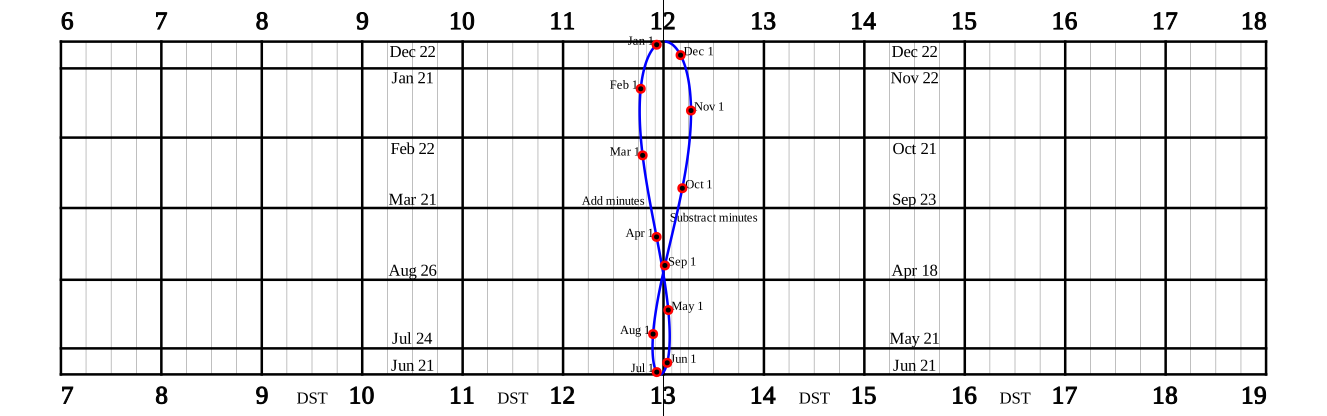
Above is the generated chart, made from my Python script. If scaled up at the same aspect ratio, the chart can be used at any size if wrapped into a half cylinder. The image here is just a JPEG image, but click on it to see the the original, downloadable, and completely scalable, SVG file.
I'll post my python code eventually. Also I want to make a html/javascript page that can generate the diagram at runtime in the browser.
Bibliography
Here are some links:- http://www.mysundial.ca/files/Standard_Time_Equatorial_Ring_Sundial_Kit_NH.pdf
- http://en.wikipedia.org/wiki/Analemma
- http://www.analemma.com/pages/framespage.html
- http://en.wikipedia.org/wiki/Equation_of_time
- http://www.esrl.noaa.gov/gmd/grad/solcalc/
- http://www.analemma.com/pages/Summation/SummationMath/EOTv12.xls
Sunday, 19 January 2014
Garbage incinerator
A couple of years ago we built a cleaner garbage incinerator. I saw a video on YouTube about a commerical system that burned garbage by gasifying the waste, and then burning the smokey gas with injected fresh air. The system burned hot and cleanly, and they claimed it met EPA regulations. I've always hated burning barrel smoke, so I wondered if something similar could be built. Looking more into this I found that several people have made their own cyclonic garbage incinerators and that they work rather well. Even better, no modifications to the barrel need to be made. All you need is the lid part with the combustion chamber, air intake and exhaust.

How it works is that the heat causes the garbage to begin to burn, but it only burns partially since the oxygen down in the barrel is limited. As this hot smoke rises, it is mixed with fresh air being blown into the combustion chamber in a swirling fashion, where it ignites. The swirling fire creates a vacuum that pulls up more smoke from the barrel, sustaining the reaction. As long as the barrel stays hot the burn remains clean. If there are a lot of plastics or rubbers in the barrel, I've seen the entire barrel glow red hot from bottom to top of the exhaust at night.
The current problem is that by the time the fire burns down into the bottom of the barrel, things are so cold that the smoke doesn't ignite up in the combustion chamber anymore and just exits. So if you load the barrel right full (but do leave some space for air in between the combustibles), it burns very well for the first 2/3, but the bottom third burns about as clean as a normal open burning barrel.
Construction
We took a normal barrel lid and cut a hole in it, the same diameter as a scrap piece of pipe we had. The pipe is about 10" in diameter (it was actually an old female ringlock end that was kind of bell-shaped, but that's not required) and about 10" tall. The actual diameter of this piece of pipe isn't that important, as long as it forms a circular combustion chamber. We welded that to the lid, covering the whole in the lid we had cut out previously, and then put a cap on the 10" pipe section with a chimney pipe sticking up from that. This forms the combustion chamber. Be sure to weld up all the seems so that no smoke, flames, or sparks will escape. On the side of the combustion chamber we welded a 2" piece of pipe sticking out at a tangent angle. This brings the air into the chamber against the side of the 10" pipe, causing it to swirl. The pipe needs to be long enough that the plastic hose that attaches it to the air source is far enough away from the barrel that it won't melt. Also the air pipe can be straight in; it doesn't have to be angled down as ours is shown. Also it doesn't matter if you put it intersecting the middle of the combustion chamber or near the top. Probably it should not be near the bottom, though.Air source
For air we used the exhaust outlet from a normal shop vac. That seems to be an idea air volume for the 55 gallon barrel. After wearing out a shopvac doing this, we are now trying to use a variable-speed leaf blower. The leaf blower can put out about 2-3 times more air volume than we need, so dialing it back is important. A normal life blower on a light dimmer seems to work also. |
| Start rubbish burning, then put on the lid and turn the air on. |
 |
| Smoke hasn't ignited yet. |
 |
| Smoke has ignited, but smoke is leaking out. |
 | |
| Good and hot now, no smoke. |
 | |
| Barrel is getting very hot, nearly 500oF and reversing the rust, turning it black again. |

Improvements
A number of improvements can be made. One is to insulate the barrel and lid with fiberglass insulation. This will keep the heat inside, which will ensure that combustibles that gassify down near the bottom of the barrel will still ignite up at the top and burn.
Another improvement might be some way to stir the materials as they burn down so that the ashes have a chance to burn. In theory, almost all combustibles should be able to burn without leaving hardly any ash behind.
We have also tried putting little fins in the combustion chamber to direct some of the swirling airflow down towards the bottom of the barrel. If the barrel was insulated, perhaps these fins would not be needed since we don't really want the fresh air going down into the barrel anyway. We'd rather have things gassify and then burn up top.
Friday, 17 January 2014
PID Loop Fun
Now that the servo valve is working (being controlled by a Solarbotics L298 compact motor driver), the next natural thing was to figure out how to get it to keep a set flow rate. Since the servo is relatively slow to move, the first and obvious thing to try is a naive, reactionary algorithm. Basically you have a loop that checks to see if the flow is where I want it and if it's too low, open the valve, and if it's too high close the valve. If you set the valve speed according to how far off the flow is from where you want it, then you really have a proportional controller, which is one third of a full PID controller. Also a naive algorithm typically has a dead band where the valve doesn't move at all. For some things like my electric hoist valve controller, this works very well. If you can get away without PID, that's often the simplest.
For this application it didn't work at all. The valve would open, the flow rate would jump suddenly to a very high number, and then the loop would react and command the valve to close, but then it would overshoot and shut the water right off, and repeat. So no control at all.
Okay, so PID is probably needed. At least I was pretty sure. There are other algorithms for doing a feedback look for other applications, but as near as I could tell my system seemed to fit the parameters of a system that could be controlled by PID. Certainly some system must work, because farm sprayers use a valve and flow meter all the time and get relatively good control over flow rates.
I settled on the PID Library by Brett Beauregard. The inputs for the library are from 0-1023. Because the motor driver takes an analog value to drive the PWM, I figured that I could set the PID outputs to -255 and 255, which was a mistake as I'll describe later. All the docs I'd read said to start tuning with the proportional variable first. So that's where I started.
And it didn't work! The same oscillations as the naive algorithm. Which in hindsight, should have been expected. If found a great article called, PID Without PhD, that explained how PID worked and how the terms work. And suggested that for my application, I needed to use the derivative term. P and I both are completely reactive, which is why I had so many problems. By the time the loop can see the effects of moving the valve, it's far too late, and so you just get oscillation. The D term is predictive. Strictly speaking it adjusts the output of the PID based on the rate of change of the input (flow rate). So it helps moderate the movement. Sounds good.
Unfortunately, while the D term helped a lot, things were still not good. Often the valve would start rapidly moving back and forth, which I thought was a bit odd. Even when the flow rate was quite a bit higher than the commanded rate, the PID output will spike up to 255 sometimes, then to -255, without any in-between. So clearly I was misunderstanding something. So I examined the PID Library code more closely. PID theory is based on some complicated-looking formulas involving calculus, but the actual calculations in the code are pretty simple. I realized that I erred in setting the output limits. The limits were merely truncating the output of the calculation, not scaling it. I might be able to adjust my PID vars to compensate, but I figured it was just easier to leave the outputs as -1023 and 1023, which it appears are the library's native range. And then I just divided the output by four to get a max of -255 and 255 to feed to the PWM of the motor driver board. Suddenly things worked a lot better.
First, here is a plot of the system's reaction when I just use the P term, to show the oscillations (which are remarkably regular in period):
 And here is a plot with some basic derivative added, showing how it reacts to changing set points:

As you can see, much better, though it still can be improved. I need to play with some factors like the Integral term. Because the servo doesn't always move at very low PWM inputs (just vibrates), sometimes the flow will sit near the setpoint but not reach it while the PID loop is commanding a steady movement, but it's too small a magnitude for the servo to actually move. With integral I might be able to get the output to increase if the flow isn't changing.
The other big problem is that because the water is under pressure, when the valve cracks open there's an initial burst of flow that is often double what the commanded set point is. The algorithm can react to this and bring it under control, but it'd be nice to not overshoot this by so much. One idea I want to try is to have it first aim for 1/2 of the set point, and then when that's achieved (and water is actually flowing), move to the real set point.
Also I may need to use adaptive tunings. Since the PID loop works with values from 0-1024, I either have to scale the sensor readings into that range, or do some kind of windowing. As well, I could have different tunings for when the flow has settled very close to desired flow.
Just for the record, the last chart was using a P value of 2, an I value of 0.01, and a D value of 1.
For this application it didn't work at all. The valve would open, the flow rate would jump suddenly to a very high number, and then the loop would react and command the valve to close, but then it would overshoot and shut the water right off, and repeat. So no control at all.
Okay, so PID is probably needed. At least I was pretty sure. There are other algorithms for doing a feedback look for other applications, but as near as I could tell my system seemed to fit the parameters of a system that could be controlled by PID. Certainly some system must work, because farm sprayers use a valve and flow meter all the time and get relatively good control over flow rates.
I settled on the PID Library by Brett Beauregard. The inputs for the library are from 0-1023. Because the motor driver takes an analog value to drive the PWM, I figured that I could set the PID outputs to -255 and 255, which was a mistake as I'll describe later. All the docs I'd read said to start tuning with the proportional variable first. So that's where I started.
And it didn't work! The same oscillations as the naive algorithm. Which in hindsight, should have been expected. If found a great article called, PID Without PhD, that explained how PID worked and how the terms work. And suggested that for my application, I needed to use the derivative term. P and I both are completely reactive, which is why I had so many problems. By the time the loop can see the effects of moving the valve, it's far too late, and so you just get oscillation. The D term is predictive. Strictly speaking it adjusts the output of the PID based on the rate of change of the input (flow rate). So it helps moderate the movement. Sounds good.
Unfortunately, while the D term helped a lot, things were still not good. Often the valve would start rapidly moving back and forth, which I thought was a bit odd. Even when the flow rate was quite a bit higher than the commanded rate, the PID output will spike up to 255 sometimes, then to -255, without any in-between. So clearly I was misunderstanding something. So I examined the PID Library code more closely. PID theory is based on some complicated-looking formulas involving calculus, but the actual calculations in the code are pretty simple. I realized that I erred in setting the output limits. The limits were merely truncating the output of the calculation, not scaling it. I might be able to adjust my PID vars to compensate, but I figured it was just easier to leave the outputs as -1023 and 1023, which it appears are the library's native range. And then I just divided the output by four to get a max of -255 and 255 to feed to the PWM of the motor driver board. Suddenly things worked a lot better.
First, here is a plot of the system's reaction when I just use the P term, to show the oscillations (which are remarkably regular in period):
As you can see, much better, though it still can be improved. I need to play with some factors like the Integral term. Because the servo doesn't always move at very low PWM inputs (just vibrates), sometimes the flow will sit near the setpoint but not reach it while the PID loop is commanding a steady movement, but it's too small a magnitude for the servo to actually move. With integral I might be able to get the output to increase if the flow isn't changing.
The other big problem is that because the water is under pressure, when the valve cracks open there's an initial burst of flow that is often double what the commanded set point is. The algorithm can react to this and bring it under control, but it'd be nice to not overshoot this by so much. One idea I want to try is to have it first aim for 1/2 of the set point, and then when that's achieved (and water is actually flowing), move to the real set point.
Also I may need to use adaptive tunings. Since the PID loop works with values from 0-1024, I either have to scale the sensor readings into that range, or do some kind of windowing. As well, I could have different tunings for when the flow has settled very close to desired flow.
Just for the record, the last chart was using a P value of 2, an I value of 0.01, and a D value of 1.
Thursday, 16 January 2014
Flow rate controller project
Lately I've been trying to get a handle on PID and how to use it to do liquid rate control using a servo valve that I made myself combined with a flow sensor. I'll add pictures tomorrow.
The valve is a ordinary plastic 3/4" ball valve with a yellow handle. I originally intended to drive it with a gear motor, but the valve does get sticky when it's all the way shut, and the motor I had couldn't move it. So I bought a cheap 2" linear actuator with limit switches but no positioning sensor. I built a simple pivot system that would mate with the handle of the valve and let the actuator turn the valve. I used the Sketch module of FreeCAD to figure out where to mount the actuator and how long of a swing arm the valve required so that full actuator motion is exactly 90 degrees on the valve. Sketch has a constraints solver, so I put in the numbers I knew and let it solve the rest. Was very slick! Ended up making the arm exactly 1.5" center to center, and mounted the actuator inline with it. I set it up at first so that the actuator opens the valve very quickly and by the time the valve is closed it's moving more slowly. The beginning angle with the arm is very shallow and the final angle is closer to 80 degrees. This turned out to be exactly backwards. Most of the flow is in the first few degrees of turning the valve. So I just swapped the actuator over to the other side of the valve (and swing the arm around) and reversed the wires. So now I get the exact same motion, but when the valve is closed I get the least shallow angle so I have the most control.


The threads on the flow sensory are 3/4" fine threads, the same pitch as NPT, but they aren't tapered. So it's hard to know how to connect to them. I ended up taking a plastic male/male coupler, cutting it down and boring the threads out a bit so it doesn't fit so tightly. I screw that onto the sensor fitting, then put in an o-ring, and then screw in another fitting. Inside the coupler they but up against the o-ring and you can screw them tightly together. This way the seal is the o-ring and not the threads. So far this is leaking in my test stand, but I think that's currently because the fittings I'm testing with are too tight into the coupler and I can't screw them together tight enough against the o-ring. I have some other fittings that will work a little better I think. I need to make whatever fittings I use such that I can easily remove the flow sensor from the system and replace it if it stops working, which is likely since it's only a $15 dollar part (commercial flow sensors with impellers are hundreds of dollars!).

Arduino interface
Interfacing the servo and flow meter with Arduino is relatively simple. The servo is 12V and I drive it with a Solarbotics L298 compact motor driver board which looks like this:
 It connects the servo motor to 12V power, and then uses three 5V signal wires from the Arduino. One to enable forward motion, one to enable reverse, and then the PWM signal to control speed. PWM goes into the motor channel's "enable" line, using analogWrite() on Arduino. The direction signals just use digitalWrite.
Not all outputs on Arduino are capable of emitting PWM right from the CPU using analogWrite. Originally I was using digital output pin 7, which couldn't do PWM. So I had to switch to Pin 6.
Some people drive these boards using PWM on the motor direction pins. This would let me use two wires to control the board instead of three by shorting enable to 5V with a resistor. This would use two PWM outputs though. The board's documentation recommends PWM on the "enable" line which is what I've done.
If I really was short on digital output pins, I could make a small circuit using transistors that would drive forward high and reverse low when a digital output is high, and then when it's low, forward low and reverse high. And then still use just one PWM for motor speed. In fact there's a little circuit in the board's documentation that allows exactly this with one transistor and a few resisters.
Servo Valve
The valve is a ordinary plastic 3/4" ball valve with a yellow handle. I originally intended to drive it with a gear motor, but the valve does get sticky when it's all the way shut, and the motor I had couldn't move it. So I bought a cheap 2" linear actuator with limit switches but no positioning sensor. I built a simple pivot system that would mate with the handle of the valve and let the actuator turn the valve. I used the Sketch module of FreeCAD to figure out where to mount the actuator and how long of a swing arm the valve required so that full actuator motion is exactly 90 degrees on the valve. Sketch has a constraints solver, so I put in the numbers I knew and let it solve the rest. Was very slick! Ended up making the arm exactly 1.5" center to center, and mounted the actuator inline with it. I set it up at first so that the actuator opens the valve very quickly and by the time the valve is closed it's moving more slowly. The beginning angle with the arm is very shallow and the final angle is closer to 80 degrees. This turned out to be exactly backwards. Most of the flow is in the first few degrees of turning the valve. So I just swapped the actuator over to the other side of the valve (and swing the arm around) and reversed the wires. So now I get the exact same motion, but when the valve is closed I get the least shallow angle so I have the most control. | |
| Valve closed. Steep angle means finer movements. |
 | |
| Valve open. Note the shallow angle. |
Flow sensor
The flow sensor is a SeeedStudio 3/4" flow sensor that is a spinning turbine that turns a magnet that sweeps past a hall sensor. This generates a PPM signal that I can read on the arduino using an interrupt and counter.
The threads on the flow sensory are 3/4" fine threads, the same pitch as NPT, but they aren't tapered. So it's hard to know how to connect to them. I ended up taking a plastic male/male coupler, cutting it down and boring the threads out a bit so it doesn't fit so tightly. I screw that onto the sensor fitting, then put in an o-ring, and then screw in another fitting. Inside the coupler they but up against the o-ring and you can screw them tightly together. This way the seal is the o-ring and not the threads. So far this is leaking in my test stand, but I think that's currently because the fittings I'm testing with are too tight into the coupler and I can't screw them together tight enough against the o-ring. I have some other fittings that will work a little better I think. I need to make whatever fittings I use such that I can easily remove the flow sensor from the system and replace it if it stops working, which is likely since it's only a $15 dollar part (commercial flow sensors with impellers are hundreds of dollars!).
Arduino interface
Interfacing the servo and flow meter with Arduino is relatively simple. The servo is 12V and I drive it with a Solarbotics L298 compact motor driver board which looks like this:
Not all outputs on Arduino are capable of emitting PWM right from the CPU using analogWrite. Originally I was using digital output pin 7, which couldn't do PWM. So I had to switch to Pin 6.
Some people drive these boards using PWM on the motor direction pins. This would let me use two wires to control the board instead of three by shorting enable to 5V with a resistor. This would use two PWM outputs though. The board's documentation recommends PWM on the "enable" line which is what I've done.
If I really was short on digital output pins, I could make a small circuit using transistors that would drive forward high and reverse low when a digital output is high, and then when it's low, forward low and reverse high. And then still use just one PWM for motor speed. In fact there's a little circuit in the board's documentation that allows exactly this with one transistor and a few resisters.
LinuxCNC
Finally got a real pci parallel port card for this Linux computer so we can use LinuxCNC to control a little 3-axis routing/dremel gantry that Eric built. (add picture later!).
The recommended OS is a special version of an old Ubuntu distribution with some real-time rtai kernel patches in it so the Parallel port can be used as a direct signalling interface for stepper motors. Turns out that rtai is somewhat deprecated in favor of a new rt system. Turns out that CERN has built kernels with the new RT system (which seems a heck of a lot easier to work with with standard posix APIs if I'm not mistaken so no funky rtai interface) that are compatible with RHEL and CentOS. They have a repository here. And also some LinuxCNC developers are moving LinuxCNC to the new system. So hopefully this means I have a working system based on something a little more modern, but still stable, than Ubuntu 10.04.
I've found a couple of programs that can generate gcode that I will integrate into my workflow. PyCAM for 3-d stuff, and the Inkscape gcodetools add-on for doing path generation for the plasma cutter, should we ever want to switch it to LinuxCNC from torchmate. Sketchup works decently well for doing 3D models that we can then machine. But maybe we'll want a real CAD program with some parametric features. FreeCAD will eventually fill the bill, but not for a few more years. So maybe in the meantime, BricsCAD for $1000?
The recommended OS is a special version of an old Ubuntu distribution with some real-time rtai kernel patches in it so the Parallel port can be used as a direct signalling interface for stepper motors. Turns out that rtai is somewhat deprecated in favor of a new rt system. Turns out that CERN has built kernels with the new RT system (which seems a heck of a lot easier to work with with standard posix APIs if I'm not mistaken so no funky rtai interface) that are compatible with RHEL and CentOS. They have a repository here. And also some LinuxCNC developers are moving LinuxCNC to the new system. So hopefully this means I have a working system based on something a little more modern, but still stable, than Ubuntu 10.04.
I've found a couple of programs that can generate gcode that I will integrate into my workflow. PyCAM for 3-d stuff, and the Inkscape gcodetools add-on for doing path generation for the plasma cutter, should we ever want to switch it to LinuxCNC from torchmate. Sketchup works decently well for doing 3D models that we can then machine. But maybe we'll want a real CAD program with some parametric features. FreeCAD will eventually fill the bill, but not for a few more years. So maybe in the meantime, BricsCAD for $1000?
Cheap RTK GPS?
We've been following Piksi RTK GPS project, but here's another one: http://www.indiegogo.com/projects/navspark-arduino-compatible-with-gps-gnss-receiver
And so I don't forget, here's a link to diydrones discussion: http://diydrones.com/profiles/blogs/affordable-centimeter-level-gps-accuracy
Unfortunately it's not clear exactly what the navspark stuff really is, even after the discussion on the diydrones forum. There's no mention of a base station, which is necessary for RTK reference calculations. And they are almost out of time on their funding, which means they probably won't make it. But they just aren't clear on exactly what they are making. The world has plenty of embedded, arduino-compatible platforms so maybe that's why they are not getting much attention.
And so I don't forget, here's a link to diydrones discussion: http://diydrones.com/profiles/blogs/affordable-centimeter-level-gps-accuracy
Unfortunately it's not clear exactly what the navspark stuff really is, even after the discussion on the diydrones forum. There's no mention of a base station, which is necessary for RTK reference calculations. And they are almost out of time on their funding, which means they probably won't make it. But they just aren't clear on exactly what they are making. The world has plenty of embedded, arduino-compatible platforms so maybe that's why they are not getting much attention.
Windows 8.1
Tonight I had the tremendous experience of installing Windows 8.1 on a little computer Eric and I built for mom and dad's TV. The old computer, an Acer Revo, was small and quiet, but couldn't handle flash video so things like BYU TV, YouTube, and General Conference were quite sluggish.
Unfortunately Microsoft won't sell the straight download version to Canadians. We have to buy the DVD for another $20, but we can also download the ISO. Go figure. Got it downloaded and onto a flash drive for installation. Installation was surprisingly fast. Windows never asks many questions, and always assumes it is the only game in town, so installation is pretty swift, especially on USB 3.0. About 15 minutes later, it's booting into Windows off the hard drive to do first-run setup. After configuring some basic privacy settings, it then asks for a Microsoft account (on-line service) login. I didn't know that if you click on the I don't have an account yet link you can then click on another link that says, I don't want to log into Windows with a Microsoft Account. So I created a blasted account which it then wanted to verify via text message. Sigh. Too bad I didn't read this link first. After finally getting things set up, I logged in and was presented with the wonderful "Start" screen, which was wonderful. Useless waste of screen space. The only useful part of it is the Search field that I used to call up control panel so I could add some "local" users.
The next item of business was to install Firefox. By now I was looking at my traditional desktop (with the new, shiny, but now useless start button on it), and IE is pinned to the task bar. So I brought it up and typed "www.google.com" in the address bar. And it loaded up the MS IE start page again. Okay, how about "mozilla.com." Same thing. I guess IE is broken. I finally had to use the bing search field to get to Mozilla's download page, and then things seemed to work. Got Firefox installed (I'm not a Google Chrome guy), and then proceeded to download everything I need to make Windows, particularly Windows 8, usable. That means first, ClassicShell. Much better! Then VLC, WinSCP, LibreOffice, Putty, Cygwin, TigerVNC. A couple of hours later and it was as useful as Windows 7! Yay! Good job, Microsoft.
Oh and then HDMI sound output didn't work. Windows kept saying it wasn't connected. Downgraded the driver to one from Intel's web site and that sort of fixed it. Might still be a problem.
Anyway, here are the reasons we didn't go with a more sane OS:
Unfortunately Microsoft won't sell the straight download version to Canadians. We have to buy the DVD for another $20, but we can also download the ISO. Go figure. Got it downloaded and onto a flash drive for installation. Installation was surprisingly fast. Windows never asks many questions, and always assumes it is the only game in town, so installation is pretty swift, especially on USB 3.0. About 15 minutes later, it's booting into Windows off the hard drive to do first-run setup. After configuring some basic privacy settings, it then asks for a Microsoft account (on-line service) login. I didn't know that if you click on the I don't have an account yet link you can then click on another link that says, I don't want to log into Windows with a Microsoft Account. So I created a blasted account which it then wanted to verify via text message. Sigh. Too bad I didn't read this link first. After finally getting things set up, I logged in and was presented with the wonderful "Start" screen, which was wonderful. Useless waste of screen space. The only useful part of it is the Search field that I used to call up control panel so I could add some "local" users.
The next item of business was to install Firefox. By now I was looking at my traditional desktop (with the new, shiny, but now useless start button on it), and IE is pinned to the task bar. So I brought it up and typed "www.google.com" in the address bar. And it loaded up the MS IE start page again. Okay, how about "mozilla.com." Same thing. I guess IE is broken. I finally had to use the bing search field to get to Mozilla's download page, and then things seemed to work. Got Firefox installed (I'm not a Google Chrome guy), and then proceeded to download everything I need to make Windows, particularly Windows 8, usable. That means first, ClassicShell. Much better! Then VLC, WinSCP, LibreOffice, Putty, Cygwin, TigerVNC. A couple of hours later and it was as useful as Windows 7! Yay! Good job, Microsoft.
Oh and then HDMI sound output didn't work. Windows kept saying it wasn't connected. Downgraded the driver to one from Intel's web site and that sort of fixed it. Might still be a problem.
Anyway, here are the reasons we didn't go with a more sane OS:
Windows 7
- Hard to find these days, and the retail box is super expensive
- OEM activation means you can never move the license to another computer
OS X
- Apparently, resolution independence means something different to Apple than it does to me. OS X provides no way to scale the UI (not even the fonts!) without using a lower screen resolution (leaving lots of things blurry), or the so-called HiDPI mode where every logical pixel is actually 4 physical pixels--which leads to a lot of blurry bitmaps though the fonts stay sharp. Apparently making the UI vector-based like GTK 3 on Linux is now is too slow. So the end result is on a big screen a few feet away you can't read the menus.
- Even with TonyMac's help, we couldn't get OS X to run well on this machine, even though it's spec'ed out exactly to specifications listed as 100% compatible on TonyMac's site. Neither Mountain Lion or Mavericks worked out for us.
Linux
- Adobe Flash is horrible on Linux. Since BYU TV and General Conference are #1 requirements for my parents, this wouldn't work well
- Finding a good distro that has up-to-date media packages while being somewhat long-lived is hard too. Fedora works well, but it needs to be wiped every year. Linux Mint might be a good choice.
- Just didn't have time to do it properly.
Projects Journal
Even though no one is going to view this blog, it's a good way to keep track of some things I'm working on. Who knows but some of the things I find in my projects might help me or others later. So this blog is a journal of sorts, though not personal. I like the idea of blogs, but I can't quite settle on the right system or software. Probably that's just an excuse; we all know I like to dream and scheme and plan without ever doing anything. Anyway, my goal for the next week is to write something each day that pertains to my projects, electronic, computer, and farm. Perhaps I can edit them later so they are more topical, rather than just day by day. Or maybe I can post several entries each day, one for each subject.
Subscribe to:
Posts (Atom)